Portable Pi Power

battery pi

I recently wrote a piece for MAKE magazine’s projects section. The text of the article follows; you can see the whole thing on the MAKE site

The versatile system-on-a-chip Raspberry Pi board seems to have something for everyone: plenty of ports for display, sound, and USB peripherals; a pin header for relaying inputs and outputs from the physical world; and space for a dedicated camera module, which makes it great platform for all sorts of video experiments.

Still, there’s one thing the Raspberry Pi doesn’t come with: a good battery power supply. Powering the board from a wall wart is fine when there’s AC power handy — but a long-lasting and reliable battery source is essential to getting the Pi away from the desk and out in the world, where it belongs. You can buy compact Pi battery packs, like the Smart Power Base (Maker Shed #MKMTS01 at makershed.com), but I decided to build a big one — and in this project I’ll show you how you can too.

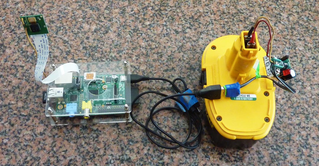
At around $40 the basic Pi board is cheap enough, but accessories (like a case, a camera, and a powered USB hub) can easily double or triple that cost. That’s one reason why I chose to power it from the same rechargeable batteries my heavy-duty cordless drill/driver uses. These 18-volt batteries are about the size of a softball — big enough to supply power for a long run, and tough enough to stand some rugged treatment. And they have another thing going for them: I already own them (along with their charger), and I suspect lots of other folks do too. Since I’m not sending my Pi aloft (yet), weight isn’t an issue. But there’s another challenge.

Trial and Error

To use these powerful batteries, you need to bring their 18 volts (or so) down to exactly 5 volts, which the Pi requires. There are several ways to do it, and I tried a few of them. First off, I made a circuit with an a 7805 linear voltage regulator I happened to have in my drawer. This IC is familiar, cheap and simple; it also fails at the task miserably, because it isn’t very efficient at voltage conversion. Mine heated up like a hot plate within minutes, letting off a smell like burning French fries and crashing the Pi (which, fortunately, was not damaged).

I also tried using a car-power charger for an iPod. The gadget I had, which sits in what used to be called a cigarette lighter socket, was rated for up to 24 volts input, and promised to deliver 1,000 milliamps at a 5-volt output: just what the Pi ordered! But alas, it didn’t work: The Pi crashed or lost contact with the server after it had run the camera for just a short time. I suspect that the charger didn’t deliver the power it was rated for, and the Pi, with the camera and the wireless dongle, simply overwhelmed it. It was time to find a better way to get power from my battery — and here’s how I did it.


power pi partslist

STEP 1

  • After checking forums and doing a web search, I found a set of components that worked well: Efficient switching regulators (such as the OKI-78SR Series by Murata) have now largely replaced the old 7800 series ICs. I chose Murata’s model OKI-78SR-5/1.5-W36-C, which delivers 1.5 amps at a 5-volt output. It can handle a range of input voltages from 7V to 36V, needs no heat sink, and is around 90 percent efficient.
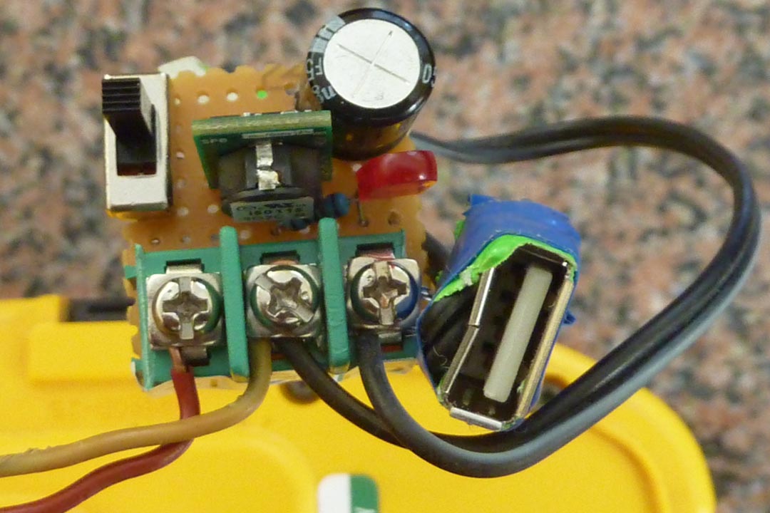
  • To complete my power converter, I added a 220µF electrolytic capacitor to help smooth the output and compensate for spikes in power demand; a mini on-off slide switch; a small red LED and series resistor, to indicate when the unit was powered; and a female USB-A jack (so I could use the same power cord that came with my AC adapter to send 5-volt power to the Pi).
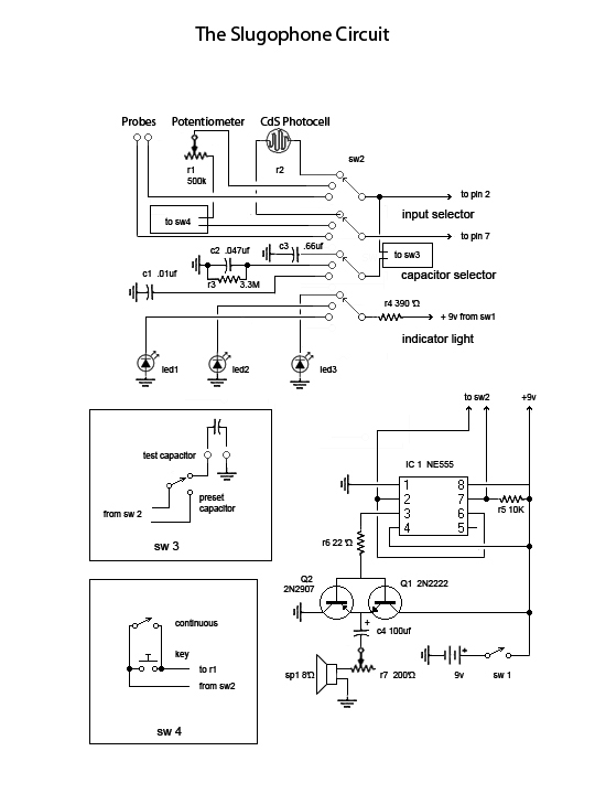
  • I also got some 18-gauge stranded wires, with an inline fuse holder and 2-amp fuse, from an auto parts store. And I picked up a small square of perforated circuit board, plus some screw terminals. The schematic for my rather simple circuit is shown here

power pi circuit

STEP 2

  • Since it might have to endure travel, neglect, or active abuse, you’ll want to make sure the power supply is a rugged, self-contained module. First, fit the screw terminals for the input and output voltages onto the bare perfboard, with their thick leads poking through the holes. One terminal takes the positive voltage in, the second is a common ground, and the third provides +5V out.
  • Next, place the switch. It may have tabs that can be slotted into the board, or lugs that are bolted on; either way, make sure it’s rigid. These are probably the largest components you’ll be using, so your board can be sized (or trimmed) accordingly. Mine is only about 1″ square.
  • Building the rest of the circuit is easy; just pay attention to the pin numbers of the regulator and the polarity of the LED and capacitor. Try to keep the component leads short, make sure nothing can get loose, and be sure to get a good solder bond.

STEP 3

  • Connect your rechargeable drill battery through the stranded wires and the 2A fuse to the screw terminals on the board. I used screw terminals so the wires can be replaced if they become frayed, or if a different type of battery is used.
  • How do you connect the wires to the battery? It depends on your battery. Mine (for older 18V DeWalt cordless tools) has spade-like positive and negative terminals in its stem. By taking a standard female automotive-type wire connector and slightly widening the receiving end, I made it fit the battery terminals perfectly. If you have a different type of battery, it might take a little ingenuity to find out what connector will work best. You’ll want a good, tight connection that won’t come loose under a little strain or jiggle.
  • Use a multimeter to verify which battery terminal is positive and which is negative. Make sure you connect them to the correct inputs on the converter board! The 2A fuse will give you some protection — but if you short it out or reverse the polarity, it may not save you from grief!

STEP 4

  • Connect the circuit board’s power output to the Raspberry Pi, either through the board’s micro-USB socket, or by connecting directly to GPIO header pins 2 and 6.
  • I prefer to use the USB socket: that way, you get protection from the board’s built-in polyfuse (which is bypassed if you use the header pins), and you keep the header free for other uses. Plus, if you need to locate the battery pack away from the camera, you can simply use an extended USB cable. However, if the circuit is constructed properly, it should work equally well supplying the GPIO pins.
  • For this build I terminated the power output with a female USB-A jack, so I can simply plug my AC adapter’s power supply cord (USB-A to micro-USB) right from the battery supply into the Pi. I wired the jack on a short length of thin, 2-conductor cable, paying careful attention to its polarity (see diagram). I could just as easily have hard-wired the jack right on the board — but I opted for the screw terminals to keep all my options open.

five components 1

STEP 5

  • After my experience with the 7805, I wasn’t about to hook this gadget up to the Pi without testing it first. Initially, I just connected the battery with nothing on the output end, flipped the switch and let it “idle” for a few minutes. I couldn’t detect any heat, and I measured 4.95V at the output terminals. Next, I placed a light-up USB toy into the socket and turned it in. Its LED light glowed brightly.
  • Finally I plugged the Pi in and booted up. It worked like a charm, both on desktop tests and in the field.
  • Recently I’ve used this battery source to make time-lapse movies up to 8 hours in length, and I haven’t had any problems. After a day of recording, I can disconnect the battery and charge it up in about 2 hours.
  • With a good-quality camera and a generous pin header for input and output, the Raspberry Pi makes a fun platform for any number of computer projects. But the various accessories you need to purchase (wireless dongle, AC power adapter, case, USB hub, etc.), let alone add-ons like a camera or TFT display, can strain an experimenter’s budget and seriously stretch the claim that it’s a “$40 computer.” Building this portable power supply that uses your rechargeable drill batteries plus about 20 bucks in parts, lets you get the Pi off your desk and out into the wild.


Welcome to our lab

Sam, Chris and Jules - the Grommets

Sam, Chris and Jules – the Grommets

Grommet Laboratories is a father-daughters collaboration that explores the interface between electronics, music and living things. The lab’s first project, which debuted at Maker Faire 2011, was the Slugophone—an insect-operated synthesizer. They followed this up in 2012 with the Musiquarium, an aquatic soundscape mediated by fish. The Grommets (Chris Losee and his daughters, Sam & Jules) are intrigued by home-made electronic gadgets, biomorphic sculpture and beam robotics. The laboratory recently acquired a raspberry pi, which will help further their investigations into physical computing.

The Musiquarium

An exotic parlor amusement retrieved from an imagined past

Winner of two Editor’s Choice Blue Ribbons at World Maker Faire 2012!

sam in dark

The Musiquarium was the second major invention of Grommet Labs, (following the Slugophone, which we introduced a year earlier), and was our second project accepted into the World Maker Faire. Our idea was to give water creatures a voice by allowing them to make musical tones as they triggered infrared sensors. As the goldfish wandered around the tank, they swam in front of various sensors—and when they did, each one produced a different sound.

We originally thought of the Musiquarium as a way to build on the idea of the Slugophone—a device that explored the interface between humans and animals, music and noise. The idea of a project that harmlessly involved live animals creating or “finding” musical sequences was the topic we were most interested in. And so we began to plan and construct the Musiquarium.

musicquarium2

We started with a small square fish tank from a pet store, and fitted a metal case around the bottom where the circuit was going to go. For its design, we employed the steampunk theme we had used with the Slugophone. Our idea was to create an aquascape evoking the remains of a crashed airship, with fragments of debris intertwined with fantastic coralline growths. The infrared sensors were then put into the tank, hidden among the decorations and gravel.

The sensors were triggered by invisible infrared light, provided by a bank of IR LEDs above the water. Some sensors were designed to produce a musical tone when a fish swam over them and blocked their light; others reacted to reflected light bouncing off the fish’s shiny scales. When a sound was triggered, an LED would light on the front of the Musiquarium; the sensitivity could also be adjusted, allowing us to “tune” the instrument. (Chris talks more about the circuit here).

The sounds triggered by each sensor were chords produced from a toy piano we picked up from a thrift shop and lovingly dissected. The toy piano also had settings for different “instruments” including bells, saxophone, xylophone, and more. We enabled the Musiquarium to produce those various sounds, as well as routing the chords through an echo delay. After two and a half months, the Musiquarium was finally completed just in time for Maker Faire 2012.

samshows musiq

The Musiquarium was a success. Visitors seemed to love it, and many stayed to hear the sounds and tune the instrument themselves. Reporters interviewed us and made videos of the machine in action—Juliana even had a sound bite on NPR’s Morning Edition radio show. Some people said they enjoyed it because it was one of the only exhibits that involved live animals. Others asked if they could buy it. We were proud to win two Editor’s Choice blue ribbon awards at the 2012 World Maker Faire. After the excitement was over, we returned to schoolwork and regular activities, all the while thinking about another project for next year.

musiq

The Slugophone

Is it music? Noise? Inter-species communication? In a word: Yes.

The Slugophone

The Slugophone

The Slugophone is a musical instrument that’s playable by anyone—even a slug. But whether you’re an insect or not, there are many ways to interact with this electronic square-wave synthesizer: You can play it like a Theremin, making eerie tones via the motion of your hand; you can grab your friends, grasp the probes, and engage in some harmonious hand-holding (or melodic thumb wars); or, relax and let a musically-inclined caterpillar make sounds as it strolls across a copper grid. The instrument is packaged in a snazzy steampunk-style case—and, of course, it comes with an elegant portable terrarium to house the obliging caterpillars.

Our development of the Slugophone began with a notion to build a gadget called “Drawdio,” a simple synthesizer attached to a pencil. This device uses the conductive properties of pencil graphite to create different sounds as you move the pencil point across the paper. We tried it out, but in the end, we weren’t satisfied with how it worked. But as we were thinking of other things we could do with a similar circuit, the Slugophone was born. My dad talks more about the circuit here.

When the basic circuit build was done, we tested it out on some live slugs to see how it worked. We also grabbed a worm and a caterpillar. The slug, unfortunately, was quite slimy (and very conductive!) It made irritating, shrill music—and worst of all, it seemed to be distressed by the copper of the circuit board; the worm produced similar results. The caterpillar, however, made the most pleasant music, and didn’t seem to mind walking around on the circuit board. So for the rest of the project, no slugs were used. The name, however, stuck.

slug on table

The Slugophone’s burnished metal case has a projecting speaker, a moveable Theremin sensor, and a series of knobs and switches on the front. These control volume, set the basic pitch range, and select input to the synthesizer: the photocell (Theremin) or the probes for humans, and the copper traces on the circuit board for insects. Here’s how it works:

The changing resistance value provided by an input device—probes, photocell, or copper grid—is transmitted to the proper pins of the 555 integrated circuit timer chip; this completes a circuit which produces different audible tones based on the resistance it’s given. For the Theremin, shading or uncovering the photocell provides the input; for the probes, it’s simply skin resistance. For the caterpillar, the changing resistance the insect’s body produced as it crawled across the copper board made new tones each time it moved.

slug crowd1

The crowd at World Maker Faire 2011 seemed to enjoy the device as much as we did. Many people played with the photo-Theremin and the synthesizer until their friends dragged them away. Others spent long periods of time gazing at the monarch caterpillar crawling across the board (We actually had two, named Angel and Lucifer; they switched off regularly, and ate leaves in between shows. When the two-day event was over, they were released unharmed in the back yard.)  All of the children wanted to touch the caterpillar, and many grown-ups were intrigued too. One spectator from a foreign country asked, in halting English, “So… caterpillar is DJ?” “Exactly,” we responded—proof that “music” can be made by anyone or anything…even a slug.

What’s Under The Hood

Going Deep Inside the Slugophone: And How to Build Your Own

Analog tone generator…or inter-species communication device?

Jules demonstrates the Slugophone.     Photo: Bonnie Hulkower
                                                  

Recently featured at the World Maker Faire in New York, the Slugophone is a last-century-style electronic organ with a twist: a fun interactive music maker, it can be used to “play” almost anything — an unwitting friend, a bouquet of flowers… even an insect!

The Slugophone is an easy project to construct, and great for learning (or demonstrating) basic circuit principles. The total cost of the project is probably $20-50, depending on what parts you already have and how fancy you want to get with the case, etc.

Education or entertainment?

With different settings of the selector switch, the Slugophone functions as:

1) A square wave audio oscillator, with continuous or keyed output;

2) A light-controlled Theremin, which produces eerie tones when you wave your  hand over a photocell, or;

3) A versatile device with external leads (probes, grid, etc) able to convert any changing resistance into a series of audio tones.

And here’s where it gets interesting. At the maker faire, we had lots of fun letting our “test subjects” play each other: each one holds a probe, and depending on how and where they touch, a different sound is generated. We also put an insect into a chamber with a circuit board on the floor, acting as a conductive grid. As it moved around, its body’s contact with the grid created a variable tone — a whole different type of insect song.

At the heart of the Slugophone is the venerable 555 IC timer chip: easily obtainable anywhere, it’s one of the most popular chips ever made. Add a few resistors, capacitors, switches and assorted doodads, and the circuit’s ready to go. You can get as fancy as you want to with the case (like our steampunk-inspired console)…but first, the basics.

slug organ-1The Square-Wave Generator

Engineers call this circuit an astable multivibrator, but you can just think of it as the tone generator. (If you google “555 tone generator,” you will find multiple examples similar to this one.) Here’s how it works: The output of the chip switches rapidly from high to low, emitting a series of pulses (a square wave) that the speaker changes into audible sound. The resistors and capacitor control how frequently the chip fires its pulses, and thus the tone it makes. Changing the resistor or capacitor values will change the tone, which can range from a slow metronome to an ultrasonic squeal.

Mixing metaphors

Think of the resistor as a beer tap, and the capacitor as a mug. As soon as the mug is completely full, the charge (I mean beer) it holds gets poured into your circuit, making it happy (I mean functional.) If you have an oversize mug (a high-value capacitor), and your tap is open only a trickle (a high-value resistor), you will be waiting a long time for the mug to fill; conversely, with a small glass and a wide-open keg, the glass fills and dumps constantly. Since the tone produced by the Slugophone is ultimately controlled by the how often the capacitor dumps its charge, choosing the right component values is critical.

Fine-tuning the circuit

In the example circuit above, a potentiometer (variable resistor) controls the charge rate of the capacitor, producing different tones.  If you just want a basic synthesizer and you have your choice of components, any number of combinations will work: I found a 500K pot, paired with a .0047uF capacitor that’s bypassed with a 3.3M resistor, gave a wide range of tones.

slug photocell circuit-1But sometimes you don’t have so many choices. For example, in the Theremin circuit, the variable resistor is a CdS photocell, which has a resistance of a few K when it’s dark, and next to nothing in bright light. Since those values can’t be changed, the capacitor must be selected to produce the widest tonal range from those resistance values. With my photocell, a relatively large capacitor of .66uF gave the best results.

slug probes circuit-1

The probe circuit may also pose a problem: depending what you’re measuring, the resistance could be large or small. I chose a compromise value for this capacitor of .01uF, since most of the things I planned to probe (like skin, plants, pets, etc) would have high resistance. Here’s what the circuits would look like in each of those cases. But wait – don’t build it yet!

Switch-hitters

cap sel sw There are two more modifications that make the circuit more versatile, and they both use switches. The first is a quick way of changing the capacitor from the one built into the circuit to another one you want to try – without having to unsolder it! This is simply a double-throw switch that bypasses the built-in component for the one you want to substitute. Both capacitors are connected to ground, so only one wire needs to be switched. The test capacitor is held in place by a spring-clip arrangement you can see on the top right of the Slugophone’s case.

slug main selector swThe second switch is a bit more complicated: It makes it possible for the Slugophone to change easily from one function to another. The one I used is a four-pole, three-position rotary switch that I found in my junk box. The nice thing about it is, it accomplishes everything with just a turn of the knob: besides sending both leads of the input resistor to the chip, it also pairs the chosen resistor with the appropriate capacitor. And to top it off, it sends current to a LED indicator light telling you which mode (organ, Theremin, or probe) the Slugphone is in. Here’s a schematic, which incorporates all three resistor-capacitor combinations, plus the test-capacitor switch and the LED indicator circuit. (If you can’t get a hold of this kind of switch, don’t worry: you can simply use a jack to hook up to your inputs, one at a time — but you may have to change the capacitor manually.)

Speak Up

slug pushpullYou probably noticed a couple of transistors hooked together by their bases at the output of pin 3, just after a resistor and before the speaker: That’s a class B push-pull amplifier. It’s needed because the output of the chip by itself isn’t strong enough to drive the speakers. Each transistor in this circuit amplifies half of the waveform, either positive or negative. After you put them together, an electrolytic capacitor (100 uF) removes stray DC voltage to leave a clearer signal. Now you’ll get plenty of sound power from the 8-ohm speaker — so much that, for the sake of decorum, a volume control (200-ohm potentiometer) has been added.

Bells and Whistles

Of course, every electronic circuit needs power, and most need to be turned off once in a while. For that, we need a 9-volt battery, a battery clip and an on-off switch. You can use a fancy lighted one if you want, but be sure it’s designed for the right voltage.

slug keysw-1By the way, did you notice that I slipped an extra switch into the drawing? Switch 4 goes on the wire between the potentiometer and the switch pole returning to pin 7 of the 555 chip. It’s actually two switches arranged in parallel, and it makes it possible to play separate notes, piano style, on the Slugphone. When the single-throw switch is closed, current always flows and a tone is constantly produced. When it’s open, notes are played by pressing on (closing) the momentary contacts of the normally-open switch. (But before you schedule a concert, keep in mind that it plays only one at a time, row-row-row-your-boat style.)

Putting it all together

Here’s a schematic diagram of the entire Slugphone circuit. It may look complicated, but it’s really just all of the pieces added together.

slugophone schematic

And that, in a very big nutshell, is what’s inside the slugophone. The great thing about this circuit is that it’s extremely versatile, and it doesn’t have a lot of critical parts. If this is your first build, take it a piece at a time, build it on a breadboard, and get each part working before you put it all together. Then go out, find a slug, and have a good time!